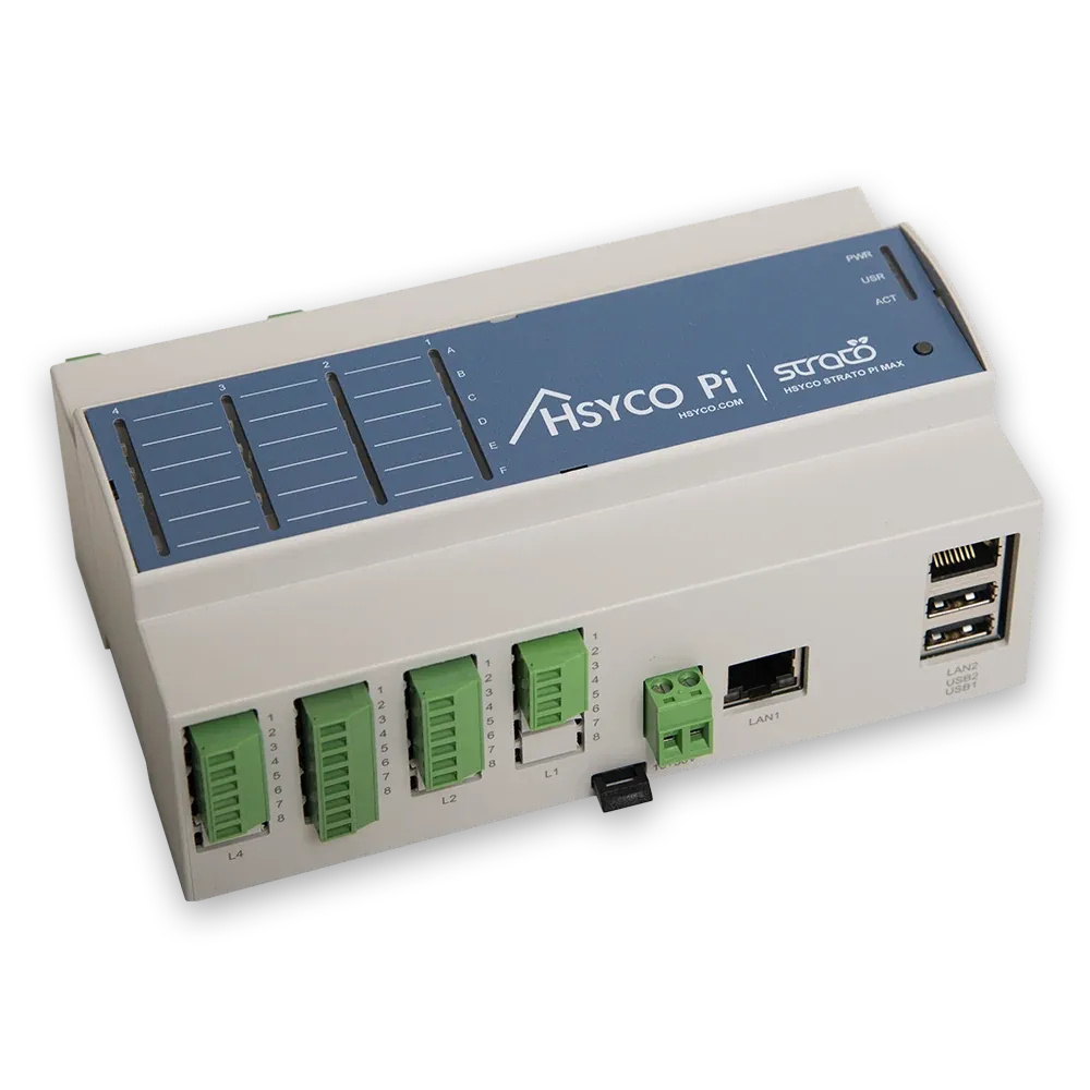
The security industry is changing rapidly. Today, it is no longer enough to connect an alarm control panel to monitoring software — companies now demand flexible solutions capable of integrating IoT sensors, different protocols, and third-party platforms.
Thanks to its native support for the SIA DC-09 protocol, HSYCO can play a key role as a bridge between heterogeneous systems.
This article presents two real-world case studies that show how HSYCO transforms complexity into transparent and effective integration.
Case Study 1: Long-distance monitoring — integrating LoRaWAN sensors into monitoring software via HSYCO
A security company must oversee not only alarms coming from customers’ intrusion panels but also from LoRaWAN sensors installed outdoors — such as motion detectors, environmental sensors, and other IoT devices.
Thanks to their long range and low power consumption, LoRaWAN devices can be installed even in areas not easily reached by traditional networks, ensuring reliable and widespread monitoring.
The challenge? These sensors do not natively speak SIA DC-09, the de facto standard for monitoring software communication.
With HSYCO, this problem is solved:
• Every message coming from the LoRaWAN network is intercepted; • HSYCO translates it into a compliant SIA message; • The monitoring software receives the event as if it had come from a traditional alarm panel.
Result: The security company manages all alarms in a single environment, regardless of the underlying technology.
How to connect a LoRaWAN device to HSYCO
How to connect a LoRaWAN device to HSYCO From an operational perspective, integrating a LoRaWAN network with HSYCO follows several key steps.
1. Configuring the LoRaWAN gateway with Semtech Packet Forwarder The gateway must support the Semtech Packet Forwarder standard. It needs to be configured to forward all uplink packets to the IP address and port where HSYCO is listening (as specified in the network server configuration). Ensure that the network (firewall, NAT, routing) allows communication between the gateway and HSYCO.
2. Declaring the LoRaWAN I/O Server in HSYCO Within the HSYCO Manager, create a new LoRaWAN I/O Server. Once defined, the LoRaWAN Utility becomes available among the manager’s applications.
3. Configuration via the LoRaWAN Utility
Open the LoRaWAN Utility to configure gateways and devices. In the Gateways tab, you can enable Auto-discovery to display gateways that are sending packets to HSYCO. Click on each gateway to edit its parameters (ID, EUI, IP address).
The gateway ID defines the prefix of the datapoints on the LoRaWAN server (e.g., gw.
4. Adding and configuring devices In the Devices tab of the LoRaWAN Utility, enable Auto-discovery: transmitting devices will appear automatically. Clicking on each device opens its configuration panel, where you can select OTAA or ABP as the activation mode. • For OTAA, specify DevEUI, JoinEUI, and AppKey. • For ABP, specify AppSKey and NwkSKey. Other configurable parameters include device class (A or C), frame counters, discard thresholds, default downlink port, and more. In the Tools panel, you can activate the frame monitor (uplink) to view packets in real time, verify counters, MIC, and decoded data (Cayenne format if enabled).
5. Committing the configuration After configuring all gateways and devices (and removing inactive ones), click Commit in the LoRaWAN Utility interface. The configuration will be saved and the LoRaWAN I/O Server restarted with the new settings.
Practical example: from LoRaWAN datapoint to SIA message
Once HSYCO receives packets from LoRaWAN sensors via the LoRaWAN I/O Server, each datapoint can be mapped to a SIA event to be sent to the monitoring software via theSIAClient I/O Server. Typical configuration:
1. Create the SIAClient I/O Server In the HSYCO Manager, declare a new SIAClient I/O Server. Specify the IP address, port, and credentials of the monitoring software that will receive the messages. Configure any encryption or authentication options supported by SIA DC-09.
2. Map LoRaWAN datapoints to SIA Each LoRaWAN sensor generates one or more datapoints on the HSYCO server (e.g., lora.dev.212.data.ch30).
3. Data flow example LoRaWAN sensor sends a message → HSYCO decodes the packet → datapoint lora.dev.212.data.ch30, value = 1
Using EVENTS the change in the datapoint’s value is linked to sending a SIA message:
IO lora.dev.212.data.ch30 = 1 : IO siaclient.message = “Nri1BA001”
The monitoring software receives the message and displays the alarm as if it had come from a traditional control panel.
4. Advantages • All sensors, even heterogeneous ones, are visible as standard SIA events. • The solution acts as a bridge without requiring changes to the LoRaWAN network or the monitoring software. • Complex rules, filters, or value transformations can be added directly in the datapoint mapping.
Case Study 2: Centralized supervision — integrating multi-brand alarm panels via Modbus with HSYCO
Consider a scenario where several alarm panels send SIA DC-09 messages to a supervision center. Each panel generates events with different formats and codes, which third-party software would struggle to interpret.
Here, HSYCO acts as aSIA SERVER:
• It receives messages from all control panels, interprets them, and organizes them into clear datapoints; • The status of sensors and alarms is made available via a Modbus/TCP table; • The external management software can read this information uniformly and instantly.
Result: The client gains a standardized and integrated view of their entire security system, without modifying the control panels’ configuration.
How to configure HSYCO as a SIA Server
1. Create the SIAServer I/O Server In the HSYCO Manager, create a new SIAServer I/O Server for each alarm panel to connect. Configure: • Listening port: the TCP port where HSYCO receives messages (e.g., 10001) • Encryption: enable if the panels support AES-128 or AES-256 encryption
2. Configure the alarm panels Each alarm panel must send its SIA DC-09 messages to HSYCO’s IP address and configured port. Ensure that: • HSYCO’s IP address is reachable from the panels’ network • Each panel uses a unique account code (e.g., PANEL01, PANEL02, etc.) • The message format complies with the SIA DC-09 standard
3. Receiving and interpreting messages
When a panel sends a SIA message, HSYCO:
• Receives it on the configured port
• Decodes the SIA DC-09 format (CRC, length, sequence, account, payload)
• Automatically creates datapoints in the format: siaserver.
Example: If PANEL01 sends a zone 5 alarm:
• Received message:
4. Exposing data via Modbus/TCP Once datapoints are available in HSYCO, they can be mapped to a Modbus/TCP table to make them accessible to third-party software (SCADA, BMS, supervision systems).
Modbus I/O Server configuration: Create a MODBUS SERVER I/O Server in the HSYCO Manager. • TCP Port: 502 (standard Modbus) or custom.
Mapping SIA datapoints to Modbus registers:
| HSYCO Datapoint | Message | Modbus Register | Type | Description |
| siaserver1.message | Nri1BA005 | Holding Register 1005 | INT16 | Alarm – PANEL 01 sensor 005 |
| siaserver2.message | Nri1BA003 | Holding Register 2003 | INT16 | Alarm – PANEL 02 sensor 003 |
| siaserver1.message | Rri1BA005 | Holding Register 1005 | INT16 | Reset – PANEL 01 sensor 005 |
| siaserver2.message | Rri1BA003 | Holding Register 2003 | INT16 | Reset – PANEL 02 sensor 003 |
You can then dynamically update the table using the EVENTS language.
Example EVENTS code: // When an alarm from PANEL01 arrives, update Modbus register IO siaserver1.message = “Nri1BA005” : IO mserver.1.1005.hr = “ushort:1”
// When an alarm from PANEL02 arrives, update Modbus register IO siaserver2.message = “Nri1BA003” : IO mserver.1.2003.hr = “ushort:1”
// When PANEL01 alarm resets IO siaserver1.message = “Rri1BA005” : IO mserver.1.1005.hr = “ushort:0”
// When PANEL02 alarm resets IO siaserver2.message = “Rri1BA005” : IO mserver.1.2003.hr = “ushort:0”
5. Reading data from external software The supervision software (SCADA, BMS, etc.) can now connect to HSYCO via Modbus/TCP and read the configured registers: • Modbus TCP connection to HSYCO_IP:502 • Read Holding Register 1005 → if = 1, Alarm from PANEL 01 sensor 005 • Read Holding Register 2003 → if = 1, Alarm from PANEL 02 sensor 003
6. Advantages of this approach • Normalization: all events from different panels are standardized into HSYCO datapoints • Interoperability: any system supporting Modbus/TCP can read statuses without understanding SIA • Scalability: new panels can be added easily without modifying the supervision software • Flexibility: HSYCO can apply custom logic before exposing data (filters, aggregations, transformations)
For more technical details, see: • SIASERVER I/O SERVER • MODBUS I/O SERVER
Why choose HSYCO
In both scenarios, HSYCO demonstrates how a single solution can simplify protocol integration and make security management more efficient. • Flexibility: translates events from different technologies (LoRaWAN, alarm panels, IoT) into standardized messages. • Centralization: allows operators to work within a single interface. • Interoperability: exposes data to other systems via standard protocols such as Modbus/TCP.
HSYCO thus proves to be a strategic solution for those who want to bring together traditional security systems and new IoT technologies — without compromising reliability or integration.